Spherical Lithium Iron Phosphate (LiFePO₄ or LFP) is one of the most important cathode materials used in modern lithium-ion batteries. It is widely applied in electric vehicles, energy storage systems, and power tools due to its excellent safety, long cycle life, and thermal stability.
However, producing high-performance spherical LFP cathode material requires a complex manufacturing process that combines materials science, chemical engineering, and powder processing technologies.
This article provides a comprehensive overview of the industrial production process of spherical lithium iron phosphate, from raw material selection to spray drying, sintering, and ultrafine grinding.
1. Why Spherical Lithium Iron Phosphate Matters
Early generations of LFP materials typically consisted of irregular particles, which created several performance limitations.
Problems with Traditional LFP Particles
- Low tap density (0.8–1.2 g/cm³)
- Wide particle size distribution
- Poor slurry stability during electrode coating
- Higher surface defects and side reactions
These factors limited the energy density and manufacturing consistency of lithium-ion batteries.
Advantages of Spherical LFP Particles
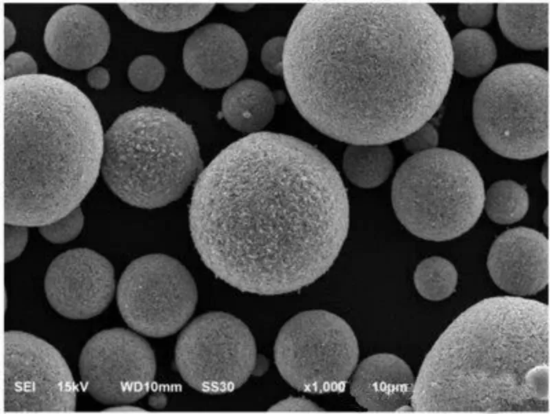
Modern LFP materials are designed as micron-scale spherical secondary particles composed of nano-scale primary particles.
This structure significantly improves battery performance.
Key benefits include:
- Higher tap density
- Better electrode compaction
- Improved slurry dispersion
- More stable electrochemical performance
Typical performance targets for spherical LFP include:
| Property | Typical Target |
|---|---|
| Tap density | ≥1.4 g/cm³ |
| Compaction density | ≥2.45 g/cm³ |
| Particle size | D10–D90: 3–25 μm |
| Specific capacity | ≥155 mAh/g |
| Cycle life | ≥2000 cycles |
2. Raw Materials and Precursor Preparation
Iron Source Selection
The choice of iron source plays a crucial role in determining both material performance and production cost.
Ferrous Oxalate Route
Advantages:
- High purity
- Excellent reactivity
Disadvantages:
- High cost
- Toxic gas generation during decomposition
Iron Phosphate Route
This is currently the most widely used industrial route.
Advantages:
- Mature production technology
- Stable product quality
- Environmentally friendly process
However, strict control of crystal water content and impurity levels is required.
Iron Oxide Route
An emerging low-cost option.
Advantages:
- Raw material cost reduction of 30–40%
However, the micron-scale Fe₂O₃ must be activated to nanoscale particles, usually through high-energy ball mill.
Lithium Source Selection
Lithium hydroxide (LiOH) is increasingly preferred over lithium carbonate.
Reasons include:
- Lower melting point (471°C)
- Faster reaction kinetics during sintering
- Improved lithium diffusion in the crystal lattice
Typical lithium hydroxide particle size:
- D50: 3–5 μm
- D90: ≤10 μm
3. Slurry Preparation and Wet Grinding
Before spray drying, raw materials must be dispersed into a stable precursor slurry.
This step determines the uniformity of the final LFP particles.
Key Process Steps
- Deionized water preparation
- Dispersant addition
- Carbon source mixing
- Iron source and phosphate addition
- Lithium source addition
- Final carbon source adjustment
Wet Grinding Process
Industrial production typically uses multi-stage bead mills.
Key control parameters include:
- Slurry temperature ≤45°C
- Dissolved oxygen ≤0.5 ppm
- Viscosity: 300–500 mPa·s
Proper grinding ensures uniform particle dispersion at the micro- and nano-scale.
4. Spray Drying Granulation
The Core Step in Spherical Particle Formation
Spray drying is the key technology used to produce spherical precursor particles.
During this process:
- The precursor slurry is atomized into droplets.
- The droplets are rapidly dried in hot air.
- Solid spherical particles are formed.
Spray Drying System
Industrial LFP spray dryers typically feature:
- Tower diameter: 6–8 m
- Tower height: 10–12 m
- Inlet air temperature: 220–280°C
- Outlet air temperature: 90–110°C
The resulting particles usually have:
- D50: 15–25 μm
- High sphericity
- Controlled internal porosity
5. High-Temperature Sintering
Sintering is the critical step that forms the LiFePO₄ crystal structure.
It also enables carbon coating, which improves electrical conductivity.
Typical Sintering Temperature Profile
Stage 1:
Room temperature → 350°C
Removal of water and organic components
Stage 2:
350°C → 550°C
Formation of amorphous precursor phases
Stage 3:
550°C → 700°C
Main crystal growth stage
Stage 4:
Controlled cooling to stabilize the crystal structure
Atmosphere Control
The sintering process is typically carried out in a nitrogen atmosphere.
Typical conditions include:
- Oxygen content ≤20 ppm
- Nitrogen purity ≥99.999%
This prevents oxidation of Fe²⁺, which is essential for high-quality LFP crystals.
6. Carbon Coating Technology
Pure LiFePO₄ has low electronic conductivity, so a carbon coating layer is required.
Common Carbon Sources
- Sucrose
- Pitch
- Glucose
- Organic polymers
A typical carbon content of 1.5–2.5% is used.
Ideal Carbon Coating Structure
- Thickness: 5–15 nm
- Uniform distribution
- Strong adhesion to LFP particles
Proper carbon coating significantly improves rate performance and cycle stability.
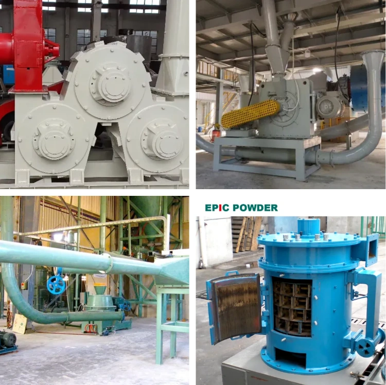
7. Ultrafine Grinding and Classification
After sintering, particles often form agglomerates.
Therefore, jet mill and air classification are required to achieve the desired particle size distribution.
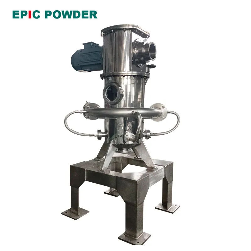
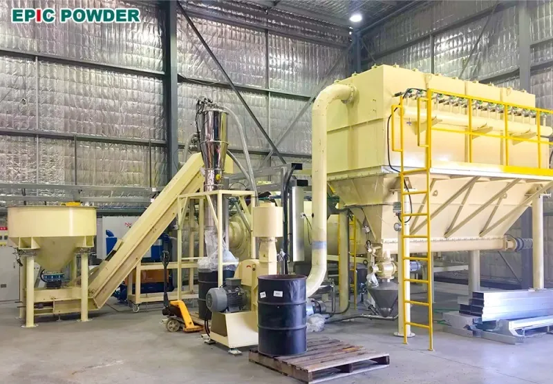
Jet Mill System
Fluidized bed jet mills are commonly used.
Typical operating parameters:
- Working pressure: 0.8–1.2 MPa
- Classifier wheel speed: 3000–5000 rpm
- Temperature control: ≤40°C
The goal is to separate agglomerates while maintaining the integrity of spherical secondary particles.
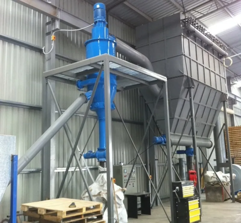
Air Classification
A multi-stage classifier system is typically used.
Classification stages:
- 25 μm → returned for grinding
- 10–25 μm → final product
- <3 μm → recycled as seed particles
8. Surface Modification and Quality Control
To further enhance battery performance, surface modification technologies may be applied.
Examples include:
- Conductive additives (carbon nanotubes, graphene)
- Silane coupling agents
- Advanced coatings such as ALD Al₂O₃ layers
These treatments improve:
- Conductivity
- Structural stability
- Cycle life
Conclusion
The production of spherical lithium iron phosphate cathode materials has evolved into a highly sophisticated industrial process.
It combines multiple advanced technologies, including:
- Spray drying granulation
- High-temperature sintering
- Carbon coating
- Jet milling and classification
- Surface modification
As the demand for electric vehicles and energy storage systems continues to grow, optimizing the LFP production process will remain critical for improving battery performance and reducing manufacturing costs.

“Thanks for reading. I hope my article helps. Please leave a comment down below. You may also contact Zelda online customer representative for any further inquiries.”
— Posted by Emily Chen